A 3-way light switch lets one light fixtureor a group of fixturesbe controlled from two different locations. You commonly find this arrangement at opposite ends of a hallway, at the top and bottom of a staircase, or beside two entrances to a large room.
Despite the name, a 3-way circuit does not require three switches. It uses two special switches, two traveler conductors, and one common terminal on each switch. Once you understand those three pieces, the wiring becomes much less mysterious. It may still look like a bowl of electrical spaghetti, but at least the noodles have job titles.
Definition and operating principles synthesized from Leviton, Eaton, Home Depot, and This Old House guidance.
Safety guidance synthesized from CPSC, ESFI, Home Depot, Lowe’s, and NFPA resources.
How a 3-Way Light Switch Works
A standard single-pole switch has two active terminals and controls a light from one location. A 3-way switch has three active terminals plus a grounding terminal. The three active connections are:
- One common terminal: Usually marked “COM” or identified by a black or dark-colored screw.
- Two traveler terminals: Usually identified by two brass or lighter-colored screws.
- One grounding terminal: Usually a green screw connected to a bare copper or green insulated grounding conductor.
The common terminal on the first switch normally receives incoming line power. The common terminal on the second switch normally sends switched power to the light fixture. The two travelers run between the switches and provide two possible paths for current.
Flipping either switch changes which traveler is connected to its common terminal. When both switches select the same traveler path, the circuit is complete and the light turns on. When they select different paths, the circuit is open and the light turns off.
That is why the words “on” and “off” are usually missing from a 3-way toggle. The physical position of either switch does not permanently represent the light’s condition.
Switch construction and traveler operation verified against Eaton, Leviton, and Lutron man
Common 3-Way Switch Wiring Layout
There are several valid ways to route cable through a 3-way circuit. Power may enter at a switch box, at the fixture, or at another junction point. The following is a straightforward modern layout frequently used when power enters the first switch box:
In this arrangement, a three-conductor cable with ground runs between the switches. Red and black are commonly used as travelers. The white insulated conductor is commonly reserved for neutral and passes through the boxes without connecting to a traditional mechanical switch.
However, older installations may use a white conductor as a traveler or another ungrounded conductor. When permitted, that conductor should be permanently reidentified with black, red, or another approved color. Never assume a white wire is neutral merely because it is white, and never assume a black wire is the incoming line without testing and tracing the circuit.
Typical layouts and alternate cable routes synthesized from Eaton, Leviton, This Old House,
Tools and Materials
For a straightforward replacement, gather the following before shutting off the power:
- A listed 3-way switch with the correct voltage and load rating
- Flat-head and Phillips screwdrivers
- A voltage tester suitable for the circuit
- Wire strippers and needle-nose pliers
- Approved wire connectors in the correct size
- Electrical tape or numbered wire labels
- A flashlight or battery-powered work light
- Safety glasses
- A phone or camera for documenting the original wiring
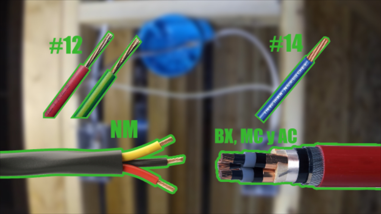
For new construction, cable size must match the branch circuit and local code. Common examples include 14-gauge copper cable on a properly protected 15-amp circuit and 12-gauge copper cable on a properly protected 20-amp circuit. Do not downsize conductors or install a device that is not rated for the circuit and connected load.
Replacing an Existing 3-Way Light Switch
Replacing one existing switch is much simpler than designing and installing a new 3-way circuit. The secret is to document the original connections before removing anything.
Step 1: Confirm That It Is a 3-Way Switch
Operate the light from both locations. If either switch can change the light from on to off or off to on, you probably have a 3-way circuit.
After de-energizing and opening the box, a conventional 3-way switch typically has three insulated conductors attached to active terminals, plus a bare or green grounding conductor. Do not count neutral wires joined together in the back of the box as switch terminals.
Step 2: Turn Off and Verify the Power
Switch off the correct circuit breaker. Place a note or breaker lock on the panel so another person does not restore power while you are working.
Remove the wall plate and test the switch, terminal screws, grounding conductor, box, and nearby wire bundles. A breaker directory can be wrong, and a multi-gang box may contain conductors supplied by more than one circuit.
Step 3: Photograph and Label Every Connection
Take clear photographs from several angles. Pay special attention to the wire connected to the black or dark-colored screw. Label that conductor “common” before loosening the terminal.
This step prevents the most common 3-way replacement error: connecting the old common conductor to one of the new switch’s traveler terminals.
Step 4: Remove the Old Switch
Loosen the terminal screws and disconnect the wires. If a conductor is inserted into a rear connection, use the manufacturer’s release method or cut and restrip it when enough conductor length is available.
Inspect the wire ends. Stop if you find burned insulation, melted plastic, brittle conductors, severe corrosion, damaged aluminum wiring, or a box that is loose inside the wall.
Step 5: Connect the Ground
Connect the bare copper or green grounding conductor to the green grounding screw on the new switch. Metal boxes may also need to be bonded with an approved grounding connection and pigtail.
Step 6: Connect the Common Wire
Connect the conductor you labeled “common” to the new switch’s black or dark-colored common terminal. Do not choose this connection based on where the screw was positioned on the old switch. Different brands may arrange their terminals differently.
Step 7: Connect the Two Travelers
Connect the remaining two switched conductors to the two brass traveler terminals. On an ordinary mechanical 3-way switch, the two travelers are generally interchangeable. Either traveler can connect to either brass terminal.
Step 8: Tighten and Inspect the Connections
Follow the stripping length and connection method printed on the device. When using a side screw, form the conductor around the screw in the direction the screw tightens unless the device specifies another method. No bare copper should extend beyond the terminal area, and insulation should not be trapped under a terminal intended to contact copper.
Use only listed wire connectors that match the number, material, and size of the conductors being joined. Tug each connection gently to confirm that it is secure.
Step 9: Fold the Wires Into the Box
Fold the conductors carefully into the box rather than forcing the switch inward. Keep grounding conductors away from exposed live terminals. Install the mounting screws, align the switch, and reinstall the wall plate.
Step 10: Restore Power and Test Both Switches
Restore the breaker and test all operating combinations:
- Operate the first switch.
- Operate the second switch.
- Return to the first switch and operate it again.
- Return to the second switch and operate it again.
Either switch should change the light’s current state regardless of the other switch’s position.
Replacement procedure and common-terminal identification synthesized from Home Depot, Lowe’s, Leviton, Eaton,
How to Wire a New 3-Way Switch Circuit
Installing a completely new circuit is more involved than replacing an existing device. It may require opening walls, routing cable, calculating electrical-box capacity, obtaining a permit, protecting cable from physical damage, and arranging an inspection.
In the common layout where power enters the first switch box and the fixture cable leaves the second switch box, the conceptual connections are:
At the First Switch Box
- Connect the incoming line hot to the first switch’s common terminal.
- Connect the red and black conductors of the inter-switch cable to the two traveler terminals.
- Splice the incoming neutral to the neutral continuing toward the second box and fixture.
- Join the grounding conductors and connect a grounding pigtail to the switch.
At the Second Switch Box
- Connect the two travelers from the first box to the second switch’s traveler terminals.
- Connect the second switch’s common terminal to the switched-hot conductor leading to the light.
- Splice the neutral from the first box to the neutral leading to the fixture.
- Join the grounding conductors and ground the switch and box as required.
At the Light Fixture
- Connect the switched hot from the second switch to the fixture’s hot lead.
- Connect the circuit neutral to the fixture’s neutral lead.
- Connect the grounding conductor to the fixture and metal box as required.
This description applies only to that specific cable route. If power enters at the fixture, if the light is positioned electrically between the two switches, or if multiple fixtures and circuits share the boxes, the connections can be substantially different. Do not improvise by matching colors to a generic internet diagram.
Common 3-Way Switch Wiring Mistakes
Putting the Common Wire on a Traveler Terminal
This often produces a light that works only when one switch is in a particular position. Move the identified common conductor to the dark common terminalbut only after shutting off and verifying the power again.
Assuming the Terminal Locations Are Universal
The common screw may be on a different side or corner of the replacement switch. Screw color and manufacturer markings matter more than physical position.
Using a Single-Pole Switch
A single-pole switch cannot replace a conventional 3-way switch while preserving control from both locations. Confirm that the replacement is labeled for 3-way use.
Disconnecting Everything Before Taking a Photograph
Once the common conductor is mixed with the travelers, troubleshooting becomes harder. A 15-second photograph can prevent an hour of detective work and several new additions to your vocabulary.
Relying Only on Wire Color
Wire colors may be faded, painted, repurposed, or incorrectly installed. Identify conductors by their connections, terminal markings, circuit function, and proper testing.
Leaving Loose Connections
A loose terminal or splice can cause flickering, intermittent operation, overheating, buzzing, arcing, or damage. Tighten terminals according to the device instructions and replace damaged components.
Forcing Too Many Wires Into a Small Box
Every box has a permitted conductor capacity. Upgrading to a bulky smart switch or dimmer may create a box-fill or wire-bending problem even when the electrical connections are conceptually correct.
Connector practices and troubleshooting patterns supported by IDEAL, ESFI, Home Depot,
3-Way Switch Troubleshooting Guide
| Symptom | Likely Cause | Recommended Response |
|---|---|---|
| The light works only when one switch is in one position. | A common conductor may be connected to a traveler terminal. | Turn off power and compare both switches with the documented original wiring. |
| Neither switch operates the light. | Open common connection, loose splice, tripped breaker, failed lamp, or fixture problem. | Check the lamp and breaker first, then inspect de-energized connections. |
| The breaker trips immediately. | Short circuit, pinched conductor, grounding fault, or incorrect splice. | Leave the breaker off and have the circuit inspected. |
| The light flickers or works intermittently. | Loose terminal, damaged switch, poor splice, or incompatible dimmer and LED combination. | Turn off power, inspect the connections, and verify product compatibility. |
| The switch buzzes, sparks, smells hot, or feels unusually warm. | Loose connection, overload, arcing, damaged device, or incompatible control. | Turn the circuit off and contact a qualified electrician. |
Using a 3-Way Dimmer or Smart Switch
A standard mechanical switch, electronic dimmer, and smart switch are not wired identically. Before buying an upgrade, confirm that the product specifically supports a 3-way or multi-location application.
Many traditional 3-way dimmer installations use one dimmer and one compatible mechanical 3-way switch. Other systems require a matching companion or accessory control. Installing two ordinary dimmers in the same circuit usually does not work unless the manufacturer specifically designed them to operate together.
Smart switches may require:
- A neutral conductor in a particular switch box
- Permanent line power at the main smart switch
- A specific traveler configuration
- A proprietary companion switch
- A hub, wireless remote, or internet connection
- LED bulbs that meet the device’s minimum and maximum load requirements
Do not assume the smart switch’s wire colors correspond directly to the existing switch terminals. Follow the exact diagram for the product model and for the location where line power enters the circuit.
Dimmer and smart-switch guidance synthesized from Lutron, Eaton, Lowe’s, and manufacture
When to Call a Licensed Electrician
Stop the project and seek professional help when:
- You cannot identify the common and traveler conductors with confidence.
- The breaker does not clearly disconnect every conductor in the box.
- The box contains wiring from multiple circuits.
- You discover aluminum branch-circuit wiring.
- Insulation is burned, brittle, cracked, melted, or discolored.
- The switch or wall plate was previously hot, buzzing, sparking, or producing an odor.
- The grounding system is missing or unclear.
- The wiring does not match any approved manufacturer diagram.
- You need to add cable, enlarge boxes, open walls, or modify the branch circuit.
- The breaker trips after the new switch is installed.
Calling an electrician is not admitting defeat. It is choosing not to use your hallway lighting as an advanced course in accidental arc welding.
Experience Notes From Real-World 3-Way Switch Projects
The most useful lesson from typical 3-way switch repairs is that the job is rarely difficult because of the switch itself. The difficulty comes from assumptions. Homeowners expect the wire on the upper-left screw of the old switch to belong on the upper-left screw of the new switch. Then they discover that the new manufacturer placed the common terminal on the opposite side. The light begins behaving like it has strong opinions about which doorway you use.
Labeling the common conductor before disconnecting the original switch prevents most of this confusion. A small piece of tape marked “COM” is more valuable than memorizing wire colors. Red and black are often travelers, but “often” is not a diagnostic method. In older homes, a white conductor may have been used as a traveler and may lack clear reidentification. In renovated homes, paint overspray can make red, white, and beige conductors look suspiciously similar inside a dim box.
Taking photographs is another habit that consistently pays off. One straight-on image may not show which wire reaches the dark screw. Photograph the switch from both sides and include the cable groups entering the box. Those wider photos can reveal whether the two travelers come from the same cable, whether neutral conductors are spliced in the back, and whether another circuit passes through the box.
Crowded boxes create a different kind of challenge. The connections may be correct, yet the switch refuses to sit flat because the conductors are packed behind it like luggage after a long vacation. The solution is not to tighten the mounting screws until the switch surrenders. Conductors should be folded deliberately, with splices placed toward the back and grounding wires kept away from active terminals. A bulky smart switch may require a larger box or a different product rather than additional pushing.
Testing also deserves more attention than simply flipping one switch and seeing the light come on. A miswired circuit can appear correct in one combination. Test both switches repeatedly from both starting positions. The goal is for either switch to reverse the current state of the light every time.
Another recurring lesson is that a “bad switch” is frequently a connection problem. Loose common terminals, poorly seated push-in connections, damaged wire ends, and incorrect traveler placement can imitate device failure. Conversely, replacing a truly worn switch will not repair burned splices or heat-damaged insulation elsewhere in the box.
Finally, experienced troubleshooting includes knowing when to stop. Unexpected voltage, two breakers feeding one box, missing grounding, aluminum conductors, scorched insulation, or repeated breaker trips are not invitations to experiment. A successful project is not merely one where the light turns on. It is one where every connection is secure, the box closes without force, the protection remains intact, and the circuit continues operating safely after the tools are put away.
Conclusion
To wire a 3-way light switch correctly, focus on circuit function rather than memorizing colors. The incoming line or outgoing light conductor connects to the dark common terminal, the two interconnecting travelers attach to the brass terminals, and the grounding conductor connects to the green screw. Neutral normally continues to the fixture instead of connecting to a basic mechanical switch.
When replacing a switch, photograph the original wiring and label the common conductor before disconnecting it. When installing a new circuit, use an approved wiring plan, properly sized conductors, listed devices, adequate electrical boxes, and all locally required permits and inspections. Most importantly, de-energize and verify the circuit before touching any conductor.