Parallel plate capacitors may look like the “vanilla ice cream” of electronics: simple, familiar, and easy to underestimate. But look closer and you will find one of the cleanest examples of how electricity, geometry, materials, and energy storage all shake hands. A parallel plate capacitor is built from two conductive plates separated by an insulating material called a dielectric. That is it. No drama, no spinning parts, no tiny wizard with a voltmeter. Yet this modest structure explains much of what happens inside real capacitors used in phones, power supplies, sensors, radios, medical devices, and printed circuit boards.
The beauty of the parallel plate capacitor is that it gives us a practical model for understanding capacitance. It helps answer big questions in a small space: How does a capacitor store charge? Why does plate area matter? Why does moving the plates closer together increase capacitance? What does a dielectric really do? And why should engineers care about electric fields, breakdown voltage, and fringing effects before stuffing a design into a tiny enclosure and hoping for the best?
In this guide, we will take a close look at parallel plate capacitors from the ground up. We will explore the formula, the physics, the design tradeoffs, and the real-world lessons that make this “simple” device surprisingly powerful. Bring curiosity. The math will behave itself.
What Is a Parallel Plate Capacitor?
A parallel plate capacitor is a capacitor made from two flat conducting surfaces placed opposite each other with a gap in between. The conductors are usually metal plates, while the gap may be air, vacuum, plastic film, ceramic, glass, paper, mica, or another dielectric material. When a voltage is applied across the plates, one plate accumulates positive charge while the other accumulates negative charge. The separated charges create an electric field in the region between the plates.
The capacitor does not store electricity in the same way a bucket stores water. A better description is that it stores energy in an electric field. The charges are separated, and that separation takes work. Once charged, the capacitor can release energy back into a circuit. This is why capacitors are used for smoothing voltage, timing circuits, filtering signals, coupling AC signals, storing brief bursts of energy, and keeping digital circuits from having tiny emotional breakdowns when current demand suddenly changes.
The Basic Capacitance Formula
The ideal capacitance of a parallel plate capacitor is described by:
C = εA / d
In this formula, C is capacitance in farads, ε is the permittivity of the material between the plates, A is the overlapping area of one plate, and d is the distance between the plates. For air or vacuum, the formula is often written as:
C = ε0A / d
Here, ε0 is the permittivity of free space, approximately 8.854 × 10⁻¹² F/m. When a dielectric material is inserted, the formula becomes:
C = κε0A / d
The symbol κ, often called the dielectric constant or relative permittivity, tells us how much the dielectric increases capacitance compared with vacuum. Air is very close to 1. Some plastics are around 2 to 4. Certain ceramics can be much higher, which is one reason ceramic capacitors can pack useful capacitance into extremely small packages.
Why Plate Area Matters
The plate area is one of the easiest parts of the formula to understand. Larger plates provide more room for charge to accumulate. If you double the overlapping area while keeping the same spacing and dielectric, the capacitance roughly doubles. This is why many commercial capacitors use rolled, stacked, or layered structures. They are not trying to win a metal origami contest; they are increasing effective surface area inside a compact body.
Imagine two parking lots for electric charge. A tiny parking lot fills quickly. A larger one can hold more cars, or in this case, more separated charge, for the same voltage. That extra charge storage shows up as higher capacitance.
Why Plate Spacing Matters
The distance between plates is just as important, but it works in the opposite direction. Smaller spacing means greater capacitance. According to the formula, capacitance is inversely proportional to plate separation. If the distance between plates is cut in half, the capacitance ideally doubles.
This happens because the opposite charges on the plates interact more strongly when they are closer together. The electric field becomes more concentrated, and the capacitor can hold more charge for the same voltage. However, the phrase “just make the gap smaller” is where practical engineering starts clearing its throat.
If the plates get too close, the dielectric may fail. Every insulating material has a dielectric strength, which is the maximum electric field it can withstand before it breaks down and begins conducting. Once breakdown occurs, the capacitor may short, degrade, arc, heat up, or fail dramatically. In electronics, “dramatically” usually means smoke, smell, and someone pretending they meant to do that.
The Role of the Dielectric
The dielectric is not just empty filler. It is a key part of capacitor behavior. A dielectric is an insulating material placed between the plates. When the capacitor is charged, molecules in the dielectric polarize slightly. Their internal charges shift in response to the electric field. This polarization reduces the effective electric field for a given amount of free charge on the plates, allowing the capacitor to store more charge at the same voltage.
In plain English: the dielectric helps the capacitor become better at being a capacitor. It increases capacitance, supports mechanical spacing between plates, and can improve voltage rating depending on material and thickness. Dielectric choice affects capacitance, leakage current, temperature stability, frequency behavior, aging, size, cost, and reliability.
Common Dielectric Materials
Air is simple and stable but has low permittivity. Plastic films such as polyester and polypropylene are common in film capacitors because they offer good insulation and stable behavior. Ceramic dielectrics can offer high capacitance in tiny sizes, though some types vary with temperature, voltage, and age. Mica and glass are valued where stability matters. Electrolytic capacitors use very thin oxide layers as dielectrics, giving high capacitance but introducing polarity, leakage, and lifetime considerations.
The parallel plate model does not describe every commercial capacitor perfectly, but it explains the foundation. Whether plates are flat, rolled, stacked, etched, or separated by microscopic layers, the same ideas keep appearing: area, distance, permittivity, voltage stress, and energy storage.
Electric Field Between the Plates
In an ideal parallel plate capacitor, the electric field between the plates is nearly uniform. Away from the edges, the field lines run straight from one plate to the other. This makes the device especially useful for teaching electrostatics because it removes much of the messy geometry found in real-world shapes.
The approximate electric field between the plates is:
E = V / d
Here, E is electric field strength, V is voltage, and d is plate separation. This relationship explains why reducing plate spacing can be both helpful and risky. A smaller distance increases capacitance, but it also increases electric field strength for the same applied voltage. If the field exceeds the dielectric strength, the capacitor may fail.
Energy Stored in a Parallel Plate Capacitor
A charged capacitor stores energy in its electric field. The energy stored can be written in several equivalent forms:
U = 1/2 CV2
U = 1/2 QV
U = Q2 / 2C
These equations are useful because they show how capacitance, charge, and voltage work together. If capacitance increases and voltage stays the same, stored energy increases. If voltage doubles, energy increases by a factor of four because voltage is squared. This is why high-voltage capacitors deserve respect. A small-looking capacitor charged to a high voltage can deliver a nasty surprise, like a tiny thunderstorm with excellent aim.
A Simple Example Calculation
Suppose you have two square metal plates, each measuring 10 cm by 10 cm. The area is:
A = 0.10 m × 0.10 m = 0.01 m2
If the plates are separated by 1 mm of air, then:
d = 0.001 m
Using C = ε0A / d:
C = (8.854 × 10⁻¹²)(0.01) / 0.001
C ≈ 88.5 pF
That is a small capacitance, but it is absolutely real. Now add a dielectric with a relative permittivity of 4, and the capacitance becomes about four times larger:
C ≈ 354 pF
This example shows why dielectrics matter. The geometry stayed the same, but the material between the plates changed the capacitor’s ability to store charge.
Ideal Model vs. Real Capacitor Behavior
The ideal parallel plate capacitor formula assumes perfectly flat plates, perfectly uniform spacing, no leakage, no edge effects, and a uniform dielectric. Real life, being the overachiever of complications, adds several effects.
Fringing Fields
At the edges of the plates, electric field lines bend outward instead of traveling straight across. This is called fringing. If the plate area is large compared with the separation distance, fringing is usually small enough to ignore. But when plates are small, oddly shaped, or far apart relative to their size, fringing can significantly affect capacitance.
Leakage Current
No dielectric is a perfect insulator. A tiny amount of current may leak through it, especially at higher temperature, higher voltage, or with aging materials. In precision timing circuits, energy storage systems, and sensor applications, leakage can matter.
Equivalent Series Resistance and Inductance
Real capacitors also include unwanted resistance and inductance. Equivalent series resistance, or ESR, affects heating and energy loss. Equivalent series inductance, or ESL, affects high-frequency behavior. At high frequencies, a capacitor may stop acting like the neat little component in a textbook and start behaving like a tiny electrical committee meeting.
Parallel Plate Capacitors in Everyday Electronics
Even when a commercial capacitor does not look like two simple plates, the parallel plate concept is hiding inside. Multilayer ceramic capacitors contain many tiny conductive layers separated by ceramic dielectric. Film capacitors use long sheets of conductor and dielectric wound or stacked together. Electrolytic capacitors rely on extremely thin dielectric oxide layers to achieve high capacitance in small volumes.
Capacitors are used for decoupling power supply pins on microchips, smoothing rectified AC into steadier DC, forming filters with resistors and inductors, tuning radio-frequency circuits, creating timing delays, storing camera flash energy, and measuring physical changes in capacitive sensors. Touchscreens, humidity sensors, pressure sensors, accelerometers, and proximity detectors can all use changes in capacitance as useful signals.
Capacitive Sensors and Measurement
A parallel plate capacitor is also a natural sensor. Because capacitance depends on area, distance, and dielectric material, changes in any of those can be measured electrically. If a plate moves closer, capacitance increases. If a dielectric changes, capacitance changes. If overlapping area changes, capacitance changes.
This principle appears in pressure sensors, where a flexible diaphragm moves relative to a fixed electrode. It appears in liquid-level sensors, where the dielectric environment changes as liquid rises. It appears in touch interfaces, where a finger changes the local electric field. In each case, the capacitor becomes a translator between the physical world and an electrical circuit.
Design Tradeoffs Engineers Must Consider
Designing with capacitors requires balancing capacitance, voltage rating, size, tolerance, temperature behavior, frequency response, leakage, and cost. A larger plate area increases capacitance but takes space. Smaller spacing increases capacitance but lowers breakdown margin. A high-permittivity dielectric increases capacitance but may be less stable over voltage or temperature. A capacitor that is perfect for smoothing power may be terrible for precision timing.
For example, a small ceramic capacitor may be excellent for high-frequency decoupling near a microcontroller. A film capacitor may be preferred for audio filtering or AC applications where stability and low loss matter. An electrolytic capacitor may be chosen for bulk energy storage because it offers high capacitance at reasonable cost, but it may not perform well at very high frequencies. The right capacitor is not always the one with the biggest number printed on it.
Common Misunderstandings About Parallel Plate Capacitors
Misunderstanding 1: A Capacitor Stores Charge Like a Battery
A capacitor stores energy by separating charge in an electric field. A battery stores energy chemically. Capacitors can charge and discharge quickly, but they usually store much less energy than batteries of similar size.
Misunderstanding 2: More Capacitance Is Always Better
More capacitance can help, but it can also slow signal transitions, increase inrush current, affect stability, or change filter behavior. Electronics design is not a buffet where you simply pile on microfarads and declare victory.
Misunderstanding 3: The Formula Works Perfectly Every Time
The formula C = εA / d is an ideal approximation. It works best when the plate area is large compared with the separation distance and the dielectric is uniform. At small scales, irregular geometries, high frequencies, and edge-dominated designs, simulation or measurement may be needed.
Practical Safety Notes
Capacitors can remain charged after power is removed. Large capacitors and high-voltage capacitors can be dangerous. Before working on power supplies, amplifiers, microwave ovens, camera flashes, or similar equipment, proper discharge procedures and safety tools are essential. Do not short large capacitors casually with a screwdriver. That method is loud, stressful, potentially damaging, and unlikely to impress anyone who understands safety.
Use rated resistors, insulated tools, proper personal protection, and verified measurements. Respect voltage ratings, polarity markings, temperature limits, and manufacturer specifications. The parallel plate model may be elegant, but real capacitors can still bite.
Experiences Related to Taking A Close Look At Parallel Plate Capacitors
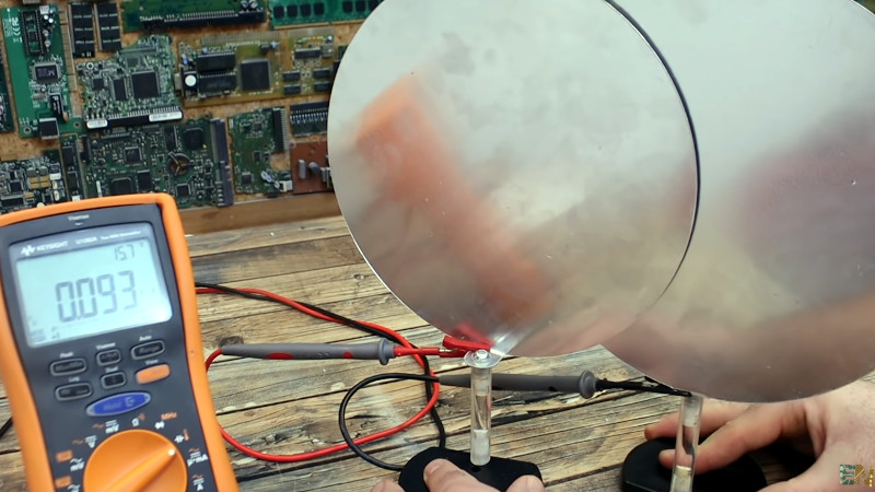
One of the most memorable ways to understand a parallel plate capacitor is to build a simple version on a workbench. Two pieces of aluminum foil, a plastic sheet, some cardboard, and a capacitance meter can teach more than a page of equations if you slow down and observe what changes. The first lesson usually arrives quickly: the capacitance is smaller than expected. That is not failure; that is reality introducing itself. The plates may not be perfectly flat, the overlap may be uneven, the dielectric thickness may vary, and the meter leads may add stray capacitance. Suddenly the tidy classroom formula becomes a starting point instead of a magic spell.
When experimenting with plate area, the behavior is satisfying. Increase the overlap, and capacitance rises. Slide one plate halfway off the other, and capacitance drops. It feels almost mechanical, like adjusting a window shade. This is a great reminder that capacitors are physical objects, not just symbols on a schematic. The geometry matters. The electric field does not care whether the drawing looked pretty in the notebook.
Changing plate spacing is even more dramatic. Press the plates closer together with a thin plastic spacer, and capacitance increases. Add extra layers of dielectric, and capacitance decreases because the effective separation grows. But this is also where the practical world taps the experimenter on the shoulder. Press too hard, and the plates wrinkle. Use an inconsistent spacer, and the reading jumps around. Move your hand near the setup, and the meter may respond because your body adds stray capacitance. Congratulations: you have become part of the circuit. Try not to let it go to your head.
A useful experience is comparing air, paper, plastic film, and glass as dielectrics. The changes may be modest in a homemade setup, but they are visible enough to make the concept real. The dielectric is not decoration. It influences how the capacitor stores energy and how stable the capacitance remains. In professional designs, this lesson grows larger. A capacitor selected only by capacitance value may behave differently under DC bias, temperature change, or high-frequency operation. The part that looked perfect in the catalog may not be perfect in the circuit.
Another practical lesson comes from measuring very small capacitances. Lead placement, cable length, nearby objects, and even humidity can affect readings. This is why careful measurement requires calibration, shielding, short leads, and sometimes guarded fixtures. The smaller the capacitance, the more the environment tries to join the conversation. Measuring picofarads can feel like weighing a feather while someone keeps opening the door.
Looking closely at parallel plate capacitors also improves intuition for printed circuit boards. Two copper planes separated by dielectric material form capacitance. Adjacent traces form capacitance. Pads, vias, connectors, and enclosures can all create unintended capacitive coupling. Sometimes that parasitic capacitance is helpful, as with power plane decoupling. Sometimes it causes crosstalk, noise, timing errors, or signal distortion. Once you understand the parallel plate model, a circuit board starts looking less like flat artwork and more like a landscape of tiny electric fields.
The biggest takeaway from hands-on experience is that capacitors are both simple and sneaky. The core idea is easy: two conductors, one insulator, an electric field. But the details matter: area, spacing, dielectric, voltage, frequency, leakage, temperature, and layout. Taking a close look at parallel plate capacitors is not just an academic exercise. It builds the kind of intuition that helps engineers choose better components, troubleshoot mysterious behavior, and design circuits that work outside the comfort zone of textbook assumptions.
Conclusion
Parallel plate capacitors are the cleanest doorway into the world of capacitance. Their basic formula, C = εA / d, shows how geometry and material properties determine charge storage. Larger plates increase capacitance. Smaller spacing increases capacitance. Better dielectric materials can increase capacitance and improve practical performance. But real capacitors add complications such as breakdown voltage, leakage current, fringing fields, ESR, ESL, temperature effects, and manufacturing limits.
The value of studying parallel plate capacitors is not limited to physics homework. The same principles appear in real electronic components, capacitive sensors, printed circuit board layouts, power supplies, radio circuits, and precision instruments. Once you understand how electric fields form between conductors, you begin to see capacitance everywhere. Sometimes it is the component you selected. Sometimes it is the hidden troublemaker you accidentally designed into the board.
So yes, the parallel plate capacitor looks simple. But simple does not mean boring. It is a compact lesson in physics, materials science, circuit design, and practical engineering judgment. Not bad for two plates and a gap.
Note: This article synthesizes established concepts commonly taught by reputable U.S. physics, electronics, engineering, and educational references. Source links are intentionally omitted according to the publishing brief.