Controlling one light from three or more locations sounds like the sort of trick a house performs after midnight. Fortunately, there is no electrical wizard hiding in the walls. The arrangement simply combines two 3-way switches with one or more 4-way switches positioned between them.
Learning how to wire a 4 way switch is mostly about understanding traveler wires, keeping cable pairs organized, and refusing to trust wire colors blindly. The physical connections are not especially complicated, but one misplaced traveler can turn a perfectly ordinary hallway light into an unpredictable puzzle.
What Is a 4-Way Switch?
A 4-way switch is a mechanical switch used to control one lighting load from at least three locations. It is commonly installed in long hallways, large rooms with several entrances, stairways with multiple landings, and garages with more doors than a sitcom set.
Despite its name, the switch does not contain four operating positions. It has four current-carrying terminals, plus a grounding terminal. Internally, it either connects two traveler paths straight through or crosses them. Flipping the switch changes those connections, which changes whether the complete circuit reaches the light.
How a Multi-Location Circuit Is Arranged
A basic three-location lighting circuit contains:
- One 3-way switch at the line or power-source end
- One 4-way switch in the middle
- One 3-way switch at the load or light-fixture end
Additional control locations can be added by placing more 4-way switches between the two 3-way switches. The 3-way devices always remain at the ends of the switching arrangement.
How a 4-Way Switch Differs From a 3-Way Switch
A 3-way switch normally has three current-carrying terminals: one darker common terminal and two traveler terminals. A standard 4-way switch has four traveler terminals arranged as two matched pairs. It does not have a common terminal.
The two terminal pairs may be identified by different screw colors, labels such as “IN” and “OUT,” or markings printed on the switch body. Terminal positions vary by manufacturer, so never assume that the two screws on one physical side form a pair. Follow the markings and the diagram packaged with the exact device.
Tools and Materials You May Need
- A listed 4-way switch with the correct voltage and amperage rating
- Insulated screwdrivers
- Wire strippers appropriate for the conductor size
- A properly rated voltage tester
- Needle-nose pliers
- Electrical tape or numbered wire labels
- Listed wire connectors, when splices or pigtails are required
- A phone or camera for documenting the original wiring
- A matching wall plate
Match the replacement switch to the circuit and existing conductors. In typical U.S. residential work, 14 AWG copper is associated with 15-amp branch circuits, while 12 AWG copper is associated with 20-amp circuits. Do not reduce conductor size, place a 15-amp-only device where a different rating is required, or rely on insulation color to determine wire gauge.
Before You Disconnect the Existing Switch
Confirm That It Is Actually a 4-Way Location
A conventional 4-way switch should have four insulated circuit conductors connected to its switching terminals, along with a bare or green grounding conductor when grounding is present. Those four insulated wires usually arrive as two traveler pairs from two separate cables or raceways.
If the device has one dark common screw and two traveler screws, it is probably a 3-way switch. If it has a neutral connection, electronic circuitry, an accessory terminal, or unusual colored leads, it may be a smart switch, dimmer, sensor, or proprietary companion device. Its installation may differ completely from a mechanical 4-way switch.
Document Every Connection
Take several clear photos before removing anything. Capture the terminal colors, printed labels, cable jackets, wire splices, grounding connections, and the direction from which each conductor enters the box.
Place matching labels on the two wires that arrive in one cable. Mark the other cable’s two travelers as a second pair. This simple step prevents the classic mistake of placing one wire from each cable on each terminal pair.
Do Not Assume Color Equals Function
Red and black are often used as travelers, but installations vary. A white conductor may also be used as an ungrounded conductor in some older or permitted cable arrangements, in which case it should be reidentified as required. Paint, previous alterations, and creative repairs can make color even less dependable.
Treat the original connections, cable grouping, device markings, testing results, and an accurate circuit diagram as evidence. Treat color as a helpful clue, not a sworn testimony.
How to Wire a 4-Way Switch Step by Step
Step 1: Turn Off and Secure the Power
Switch off the branch-circuit breaker supplying the lighting circuit. Tell everyone in the building that electrical work is underway, and use an appropriate breaker lockout device when available. A strip of tape with an angry handwritten warning is better than silence, but it is not a substitute for proper lockout procedures.
Step 2: Verify the Circuit Is De-Energized
First test your voltage tester on a known energized source. Then check the switch, every insulated conductor, grounding conductors, the electrical box, and nearby devices that may be supplied by another circuit. Finally, recheck the tester on the known live source to confirm that it remained functional.
A non-contact tester can provide an initial warning, but it has limitations. Qualified users should follow the tester manufacturer’s instructions and use an appropriate contact tester or meter when necessary to verify the absence of voltage.
Step 3: Remove the Wall Plate and Switch
Remove the wall plate and device mounting screws. Pull the switch forward carefully without yanking or sharply bending the conductors. Confirm the absence of voltage again now that the terminals are accessible.
Inspect the box before continuing. Stop if you see melted insulation, scorch marks, brittle conductors, corrosion, loose splices, undersized wires, aluminum branch-circuit wiring, or evidence that water has entered the enclosure.
Step 4: Identify the Two Traveler Pairs
Locate the two insulated travelers coming from one cable and label them as Pair A. Label the two travelers from the other cable as Pair B. When replacing an existing working switch, note which pair was attached to each matched set of terminals.
The important rule is simple: both travelers from the same cable normally connect to the same identified terminal pair on the 4-way switch. Pair A goes to one matched pair, and Pair B goes to the other.
Step 5: Disconnect the Old Device
Loosen the terminal screws and remove the conductors without damaging them. If the wires were inserted into rear clamp openings, follow the device instructions for releasing them. Avoid reusing damaged wire ends.
Cut and restrip a conductor only when enough length remains in the box and doing so complies with local requirements. Use the stripping gauge printed on the new switch or the length stated in its instructions. Excess bare copper outside a terminal can create an accidental short; too little exposed copper may produce a weak connection.
Step 6: Connect the Grounding Conductor
Connect the bare or green equipment-grounding conductor to the green grounding screw as directed by the manufacturer. Maintain grounding continuity to other devices and metal boxes using approved splices and pigtails where required.
Grounding and bonding are not decorative extras. They provide an intentional fault-current path that helps protective equipment operate when energized metal parts develop a fault.
Step 7: Connect the First Traveler Pair
Attach both travelers from Pair A to one matched terminal set. Depending on the switch, that set might use two black screws, two brass screws, two terminals labeled “IN,” or another manufacturer-specific marking.
On screw terminals, form hooks in the direction the screws tighten unless the device uses pressure plates or rear clamps. Keep insulation close to the terminal without placing insulation under a contact intended for bare copper. Tighten each terminal to the torque specified by the manufacturer rather than applying the traditional “tight enough to frighten the screw” method.
Step 8: Connect the Second Traveler Pair
Attach both travelers from Pair B to the other matched terminal set. Do not connect one conductor from Pair A and one from Pair B to each set. That crossed pairing is one of the most common reasons a newly installed 4-way switch works only in certain switch positions.
Step 9: Leave the Neutral Splice Alone
A standard mechanical 4-way switch generally does not connect to the neutral conductor. Neutrals usually remain joined in the back of the box and continue toward the light.
Do not separate or repurpose a neutral splice simply because the switch has an inviting empty area nearby. Smart switches and electronic controls may require neutral or proprietary companion wiring, but those products must be installed according to their specific diagrams.
Step 10: Inspect and Mount the Switch
Gently tug each connected conductor to verify that it is secure. Confirm that no bare copper is exposed beyond the terminals, the traveler pairs are correctly grouped, the ground is connected, and no insulation was pinched or cut.
Fold the conductors into the box in smooth bends. Avoid forcing the device against a crowded mass of wires. A box that cannot accept the device without extreme pressure may have a box-fill or conductor-management problem that requires correction.
Mount the switch, align it, and install the wall plate. Unlike a single-pole switch, a 4-way device usually has no permanent ON or OFF orientation because the light’s state depends on the positions of all switches in the circuit.
Step 11: Restore Power and Test Every Location
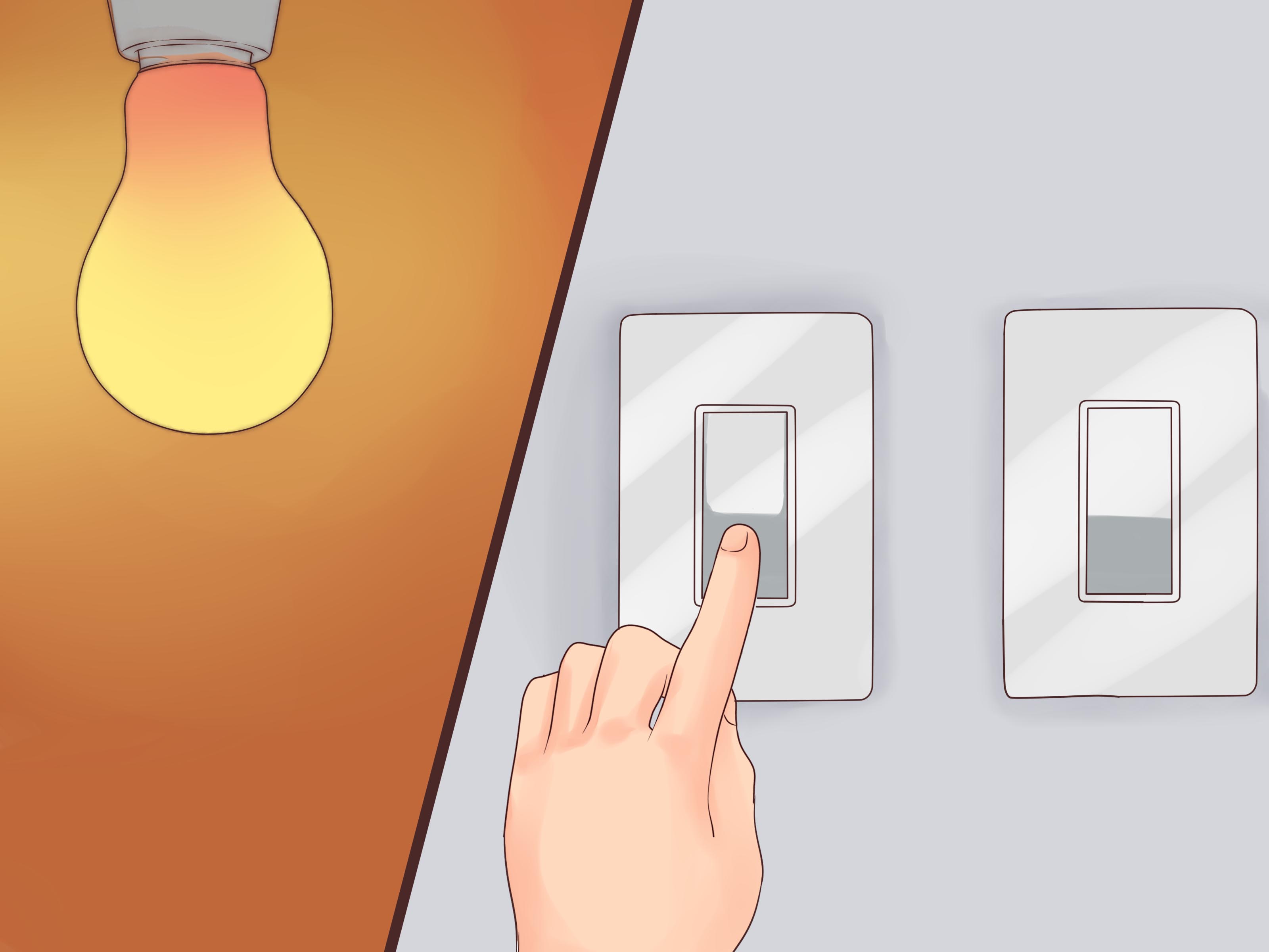
Stand clear of the box and restore the breaker. Operate each switch individually. Each control should change the light from on to off or off to on, regardless of the other switches’ positions.
Cycle through several combinations rather than flipping each switch once and declaring victory. A mispaired traveler can hide until the other switches are placed in particular positions.
Common 4-Way Switch Wiring Problems
The Light Works Only in Certain Switch Positions
The traveler pairs may be mixed at the 4-way switch, or a traveler may be connected to the common terminal of one of the 3-way switches. Turn the breaker off, verify the absence of voltage, and compare every connection with the applicable diagram.
The Breaker Trips Immediately
Do not repeatedly reset it. An energized conductor may be touching ground, a terminal may be contacting a metal box, insulation may be damaged, or conductors may be incorrectly joined. Leave the breaker off until the fault is located and repaired.
One Switch Does Nothing
A conductor may be loose, a terminal may not be clamping the wire, the switch may be defective, or the wrong type of switch may have been installed. Mechanical 3-way and 4-way switches are not interchangeable merely because both lack familiar ON and OFF labels.
The Switch Buzzes, Flickers, or Feels Warm
Stop using the circuit. Possible causes include a loose termination, an incompatible dimmer, an overloaded device, damaged conductors, or a failing switch. Slight warmth can be normal for certain electronic controls, but a standard mechanical switch should not be hot, discolored, or producing an audible buzz.
A Smart Switch Will Not Work With the Existing 4-Way
Many smart switches and dimmers use proprietary accessory devices instead of standard mechanical 3-way and 4-way switches. Some require a neutral, a specific main-device location, reconfigured travelers, or programmed companion controls. Check the exact model’s official instructions before purchasing or connecting it.
When to Call a Licensed Electrician
Professional help is the sensible choice when:
- The existing connections cannot be documented confidently
- The box contains more than one circuit
- Testing produces unexpected voltage readings
- The home has aluminum branch-circuit conductors
- Insulation is brittle, burned, melted, or cloth-covered and deteriorating
- No reliable grounding path is present
- The electrical box is overcrowded or damaged
- You are adding a new control location rather than replacing an existing switch
- The installation involves smart controls, dimmers, sensors, or mixed manufacturers
- Local rules require a permit, inspection, or licensed contractor
Replacing a clearly identified device can be a manageable project for a knowledgeable homeowner. Diagnosing altered or undocumented wiring is a different assignment, and electricity does not award bonus points for confidence.
Practical Experience: Lessons That Make 4-Way Wiring Easier
Real-world 4-way switch replacements tend to become difficult for organizational reasons rather than because the switch itself is mysterious. The installer removes the old device, four nearly identical wires spring out of the box, and suddenly everyone is participating in an electrical memory contest. The best experience-based lesson is therefore to slow down before disconnecting anything.
Photographs should be taken from multiple angles, not just straight at the front of the device. A front-facing image may show the wires but hide the cable jackets and terminal colors. A useful photo captures which conductors enter the box together, where each one lands, and how grounds and neutrals are spliced. Adding small labels such as A1, A2, B1, and B2 takes less than a minute and can prevent an hour of troubleshooting.
Another recurring lesson is that screw position is less reliable than screw color or printed markings. On one switch, the matching terminal pairs may be located on opposite sides. On another, each pair may share one side. Installing the replacement by copying physical positions from a different model can scramble the travelers even when every wire appears neatly connected.
Box organization also matters more than beginners expect. Four travelers, grounding conductors, neutral splices, and neighboring switches can create a crowded enclosure. Stuffing the new device into place may loosen a connection or push a bare grounding conductor against an energized terminal. Experienced installers fold conductors deliberately, keep grounding conductors away from live terminals, and stop when the device requires unreasonable force to fit.
Testing should be systematic. After restoring power, begin with the light on and toggle each control. Then change the position of another switch and repeat the process. A circuit may appear correct during one quick test yet fail in another combination. The requirement is not merely that the light turns on once; every switch must reverse the light’s current state from every valid arrangement.
One especially useful diagnostic clue is partial operation. When the light works from all locations only while one switch is in a particular position, the problem is often a traveler-pair error or a misplaced common conductor at an endpoint 3-way switch. When the breaker trips, however, the situation is no longer a logic puzzle. Power should remain off while the circuit is inspected for a short, damaged insulation, or contact with grounded metal.
Older homes introduce additional surprises. White wires may be used as reidentified travelers, grounding may depend on a metal raceway, and previous owners may have replaced switches without preserving the original arrangement. Some boxes contain conductors from separate breakers. Finding one dead wire does not prove that every wire in the box is dead, which is why each conductor must be tested.
The final lesson is knowing when a “simple switch replacement” has stopped being simple. Unidentified aluminum wiring, scorched terminals, brittle insulation, overloaded boxes, and unexplained voltage are not obstacles to power through. They are reasons to close the project safely and bring in a qualified electrician. Good electrical work is not defined by finishing every job alone. It is defined by leaving the installation safer than it was before the cover plate came off.
Conclusion
To wire a 4-way switch correctly, remember the basic architecture: two 3-way switches occupy the endpoints, and the 4-way switch sits between them. The middle device receives two traveler pairs, with both conductors from one cable connected to one matched terminal set and both conductors from the other cable connected to the remaining set.
Label the wires, follow the markings on the exact switch, preserve neutral splices, maintain grounding, tighten terminals to the manufacturer’s specifications, and test every control combination. Most importantly, never work on conductors until the circuit has been switched off and independently verified as de-energized.